A common question we get from our customers is about oil consumption through the PCV system. This can especially be an issue in high performance applications where PCV airflow is increased, or custom and aftermarket valve covers are used.
The first reaction of many users is that if the PCV system is consuming a lot of oil through the engine, that the PCV valve must be at fault. While running a properly tuned PCV valve is the most important step to having a properly functioning PCV system, this alone will not guarantee that oil consumption will not be excessive if the PCV valve is not properly baffled. The following experiment shows just how dramatically oil consumption through the PCV system can be reduced with proper baffle design.
Please note that this article concerns oil consumption where oil is being burned in the engine, drawn in through the PCV hose due to improper baffling. If your engine has oil dripping from the valve cover breathers, this is not a baffling issue, it means your PCV system does not have adequate airflow. A Dual Flow Adjustable PCV Valve can be used in this situation to guarantee the PCV’s airflow matches the engine’s requirements.
Test Vehicle / Engine
- 1964 Ford Fairlane
- 302 cubic inch small block
- Comp Cams hydraulic roller – .565″/.574″ lift, .232/.240 duration @ .050″
- 10:1 compression
- M/E Wagner DF-17 Dual Flow PCV Valve with DF-17-INL inline adaptor
- DF-17 PCV Valve run in fixed orifice mode, idle screw at 1-1/2 turns open
- Air-oil separator used to monitor oil consumption
Baffle #1 Testing (Excessive Oil Consumption)
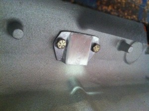
The picture below shows the first version of the valve cover baffle. Intuitively, it seemed that this design would provide enough shielding from oil splashing inside the valve covers.
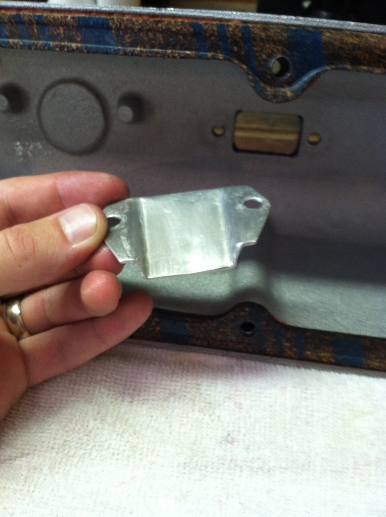 The baffle formed a small tunnel shape when bolted to the underside of the valve cover.
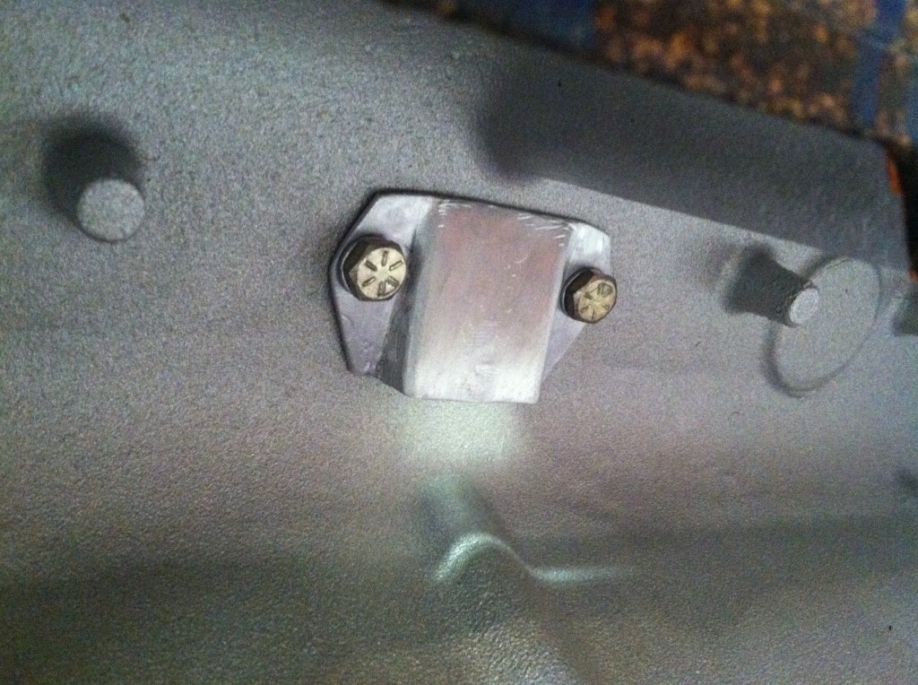 Initial tuning of the car during showed that oil consumption through the PCV system might be an issue. To quantify this, an air-oil separator was installed in the PCV system to monitor the amount of oil drawn through the PCV line.
Two controlled tests were performed. Mileage was logged, and at the end of the drive period the air-oil separator was drained. The amount of oil drained from the separator was accurately measured using a syringe.
The computed results on the right show (after a bit of math and conversion factors) how many miles would need to be driven to consume 1 quart of oil at the rate measured. Clearly this baffle was not functioning properly, since after around 600 miles a quart of oil would be consumed through the PCV system.
Further investigation showed the weakness of this baffle. Even though it adequately covered the opening in the valve cover, the “tunnel” shape it created next to the valve cover was a problem. Once air started to flow through this tunnel, any oil that was splashed around the lip of the baffle was drawn up onto the backside of the baffle. Eventually a pool of oil started to form, and the airflow rushing past this oil pool prevented it from ever draining back into the valve cover. This pool would periodically get big enough to cause a splash to get sucked up into the PCV hose.
We covered the breather stack with a piece of plexiglass to enable viewing the oil splash around the baffle. (This area is usually capped with a solid metal cap). The oil splash can be seen in the video below. Look near the bottom lip of the baffle, the oil pool can be seen even under idle conditions. Presumably at higher RPMs this situation would only become worse:
Baffle Design #2 Testing (Oil Consumption Fixed)
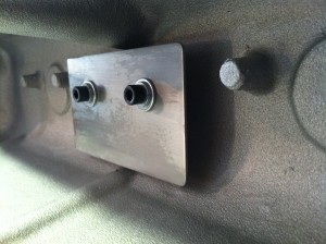
To remedy the problem, a new baffle was fabricated. This baffle used standoffs to space the entire baffle away from the valve cover. This particular baffle was spaced away from the underside of the valve cover by 3/4″, so no part of the baffle was in contact with the valve cover itself. The baffle was constructed from 16 gauge stainless sheetmetal and measured 2-1/2″ x 4-1/4″.
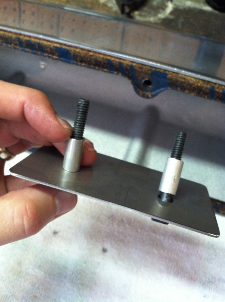
Also, the opening through which the air flows was made much bigger with this design. Where the old design had a small opening, which caused the airflow to move very quickly through it and trap oil in its path, the new design has plenty of room to allow the air to move more slowly through the system. This prevents oil splash from being pulled into the quickly moving airstream, and being drawn into the PCV system.
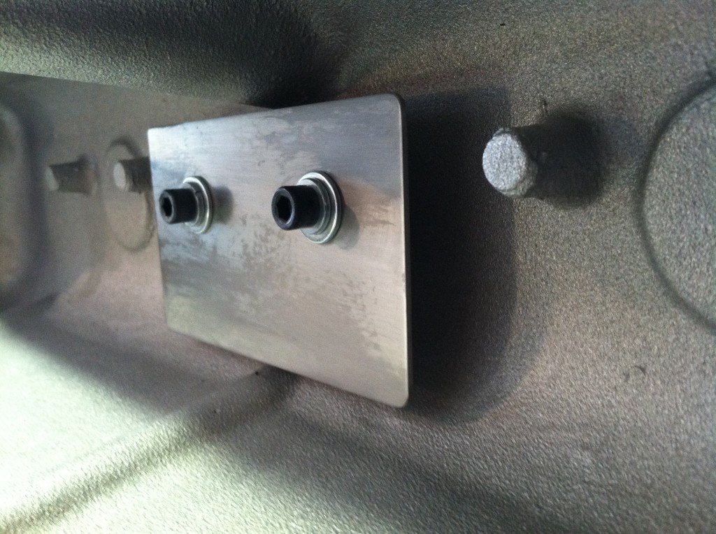
Two more drive cycles were then logged. This test used the same PCV flow rates as the last test, the only variable changed was the valve cover baffle.
The results on the right show the dramatic difference from the first design. The new configuration would require almost 30,000 miles of driving to consume 1 quart of oil through the PCV system. This is an improvement of about 50x from the previous design, all without restricting airflow through the PCV system. The crankcase is still properly ventilated, and the oil consumption has been reduced to an acceptable level.

Summary and Recommendations for Baffle Design
- There should not be a direct line of sight between the oil splash area and the inlet to the PCV system
- No part of the valve cover baffle should touch the underside surface of the valve cover if possible
- The baffle should be spaced away from the underside of the valve cover (our design used a 3/4″ gap)
- The clearance from the bottom of the PCV valve to the baffle surface should be checked. A minimum of a 3/8″ gap is recommended.
- The opening through which air flows from the oil splash area into the PCV system should be as large as possible. This prevents quickly moving air from trapping oil in the moving airstream.
